Manual Air Valve: A Comprehensive Guide
This guide delivers essential knowledge on manual pneumatic valves for U.S. industry, covering types, selection, applications, and maintenance for optimal performance.
Manual air valves are fundamental components within compressed air systems, offering straightforward control over airflow without relying on automated power sources. These valves are crucial for various industrial applications, providing a reliable means to start, stop, or redirect air flow as needed. Understanding their functionality and diverse types – including ball, butterfly, gate, globe, plug, needle, check, and angle seated valves – is paramount for efficient system operation.
This comprehensive guide explores the intricacies of manual air valves, detailing their applications, specifications, installation, maintenance, and safety considerations. We will delve into the different operator styles, like top-mounted handwheels, and examine relevant standards and regulations. Ultimately, this resource aims to equip professionals with the knowledge to select and utilize the optimal manual air valve for their specific needs.
What is a Manual Air Valve?
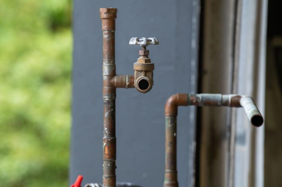
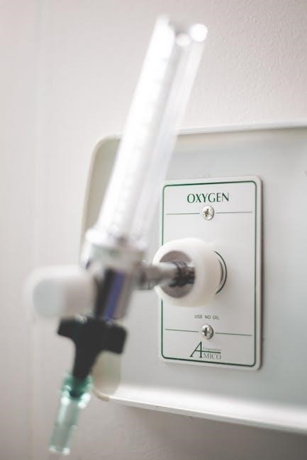
A manual air valve is a mechanically operated device used to control the flow of compressed air within a pneumatic system. Unlike automatic valves, they require direct human intervention – typically through a handle, lever, or handwheel – to open, close, or throttle airflow. This direct control makes them ideal for applications where precise, on-demand adjustments are necessary, or where automated systems are impractical or cost-prohibitive.
These valves function by physically obstructing or allowing passage through a designated pathway. They are integral to numerous industrial processes, offering a simple yet effective method for managing air pressure and direction. Their robust design and lack of reliance on electricity contribute to their reliability and longevity in demanding environments.
Types of Manual Air Valves
Manual air valves come in a diverse range of designs, each suited for specific applications and performance requirements. Common types include ball valves, known for their quick quarter-turn operation and tight shut-off; butterfly valves, offering efficient flow control in larger diameter pipes; and gate valves, ideal for fully open or fully closed service but not throttling.
Globe valves provide precise flow regulation, while plug valves offer a simple, reliable on/off function. Needle valves excel in fine flow adjustments, and check valves ensure unidirectional flow, preventing backflow. Angle seated valves are designed for specific applications requiring angled connections. Selecting the appropriate type depends on factors like pressure, flow rate, and media compatibility.
Ball Valves
Ball valves are a prevalent choice in pneumatic systems due to their simplicity and efficiency. They utilize a hollow, perforated, and pivoting ball to control flow – a quarter-turn operation provides quick on/off functionality. This design ensures minimal pressure drop when fully open, maximizing airflow;
Their robust construction makes them suitable for a wide range of pressures and temperatures. Ball valves offer a tight shut-off, preventing leakage, and are relatively inexpensive. Common materials include brass, stainless steel, and PVC, depending on the application’s requirements. They are frequently used in compressed air lines for isolation and control purposes, offering reliable performance.
Butterfly Valves
Butterfly valves represent a cost-effective solution for controlling airflow in pneumatic systems, particularly in larger diameter pipelines. They operate on a simple principle: a rotating disc controls fluid flow. A quarter-turn rotation opens or closes the valve, providing relatively quick operation.
While not offering the same level of tight shut-off as ball valves, butterfly valves excel in applications where some leakage is tolerable. They are lighter and generally less bulky than other valve types, making them suitable for space-constrained environments. Common materials include aluminum, stainless steel, and coated metals. They are frequently used for throttling and isolation in compressed air distribution systems.
Gate Valves
Gate valves are primarily designed for on/off service, meaning they are best suited for fully open or fully closed positions, not for throttling airflow. They utilize a gate – a flat or wedge-shaped disc – that slides perpendicularly to the flow path to control fluid passage.
These valves offer minimal flow restriction when fully open, resulting in low pressure drop. However, they are relatively slow to operate, requiring multiple turns to fully open or close. Gate valves aren’t ideal for frequent operation due to potential wear on the gate and seats. They are commonly constructed from materials like cast iron, stainless steel, or brass, and are often found in main air supply lines where infrequent isolation is needed.
Globe Valves
Globe valves are characterized by their spherical body and internal baffle, offering excellent flow control capabilities, making them suitable for both on/off and throttling applications. Unlike gate valves, they don’t require full rotation to operate; a relatively small turn of the handwheel can significantly alter airflow.
However, this design introduces more flow restriction and a higher pressure drop compared to gate or ball valves. The tortuous path the air takes through the valve contributes to this. Globe valves are frequently used in applications requiring precise airflow regulation, such as controlling the speed of pneumatic cylinders or regulating air pressure to specific components. Common materials include brass and stainless steel.
Plug Valves
Plug valves utilize a cylindrical or conical plug with a bore that rotates inside a valve body to control airflow. They offer a quarter-turn operation, similar to ball valves, providing quick opening and closing capabilities. However, unlike ball valves, plug valves generally offer tighter shut-off characteristics, minimizing leakage.
Different plug designs, such as straight-through or multi-port, cater to various application needs. Lubricated plug valves are common for demanding services, reducing friction and wear. While generally robust, plug valves can experience higher torque requirements than ball valves, especially in larger sizes. They are frequently found in applications needing reliable shut-off with minimal pressure drop.
Needle Valves

Needle valves are precision flow control valves characterized by a long, tapered needle-shaped plunger that moves within a corresponding seat. This design allows for very fine adjustments of airflow, making them ideal for applications requiring precise metering. Unlike on/off valves, needle valves excel at throttling – gradually regulating flow rates.
They are not typically used for large volume flow, as the small flow path creates significant pressure drop. Needle valves are commonly constructed from metal, ensuring durability and compatibility with various air system components. Applications include regulating air supply to pneumatic instruments, calibrating airflow, and controlling the speed of pneumatic actuators where precise control is paramount.
Check Valves
Check valves are fundamentally one-way valves, designed to prevent backflow in a compressed air system. They operate automatically, allowing air to flow in only one direction and immediately shutting off flow in the reverse direction. Unlike other valve types, check valves don’t require manual intervention for operation; pressure of the air itself dictates their function.
This makes them crucial for protecting sensitive pneumatic equipment from damage caused by reverse airflow or pressure surges. Common applications include downstream of filters and regulators, preventing contamination from flowing back into the system, and in air lines supplying pneumatic cylinders to maintain position when air supply is interrupted. They ensure system integrity and safety.
Angle Seated Valves
Angle seated valves represent a specialized design within manual air valves, characterized by their unique flow path that enters at a 90-degree angle to the seat. This configuration offers several advantages, notably a reduced tendency for water to accumulate and freeze within the valve body, making them ideal for outdoor applications or environments prone to moisture.
The angled design also promotes efficient flow and minimizes pressure drop. They are frequently employed in applications requiring tight shut-off and precise control, such as process control systems and pilot plant operations. Their robust construction and reliable sealing capabilities ensure long-term performance and minimal maintenance requirements.
Applications of Manual Air Valves
Manual air valves find widespread application across diverse industries, serving as critical components in pneumatic systems. Manufacturing facilities heavily utilize them for controlling compressed air powering automated machinery, tools, and robotic systems. In the automotive sector, they regulate air supply for braking systems, suspension, and various pneumatic tools used during assembly and maintenance.
Furthermore, they are essential in HVAC systems for controlling airflow and damper positions. Many manufacturing companies apply compressed air, necessitating reliable valve control. Other applications include food and beverage processing, chemical plants, and pharmaceutical manufacturing, where precise and dependable air control is paramount for process efficiency and safety.
Manual Operators for Control Valves
Manual operators provide a straightforward method for controlling valves when automated systems aren’t necessary or during maintenance. There are three primary types commonly employed. Top-mounted handwheel operators, frequently used with linear pneumatic actuators, allow for precise adjustment and are easily accessible. These operators enable manual override capabilities, crucial for troubleshooting or bypassing automated controls.
Other options include lever operators, offering quick quarter-turn operation, and direct drive operators, which connect directly to the valve stem for immediate control. The selection of an operator depends on the valve type, required force, and the specific application needs, ensuring reliable and responsive manual control.
Top-Mounted Handwheel Operators
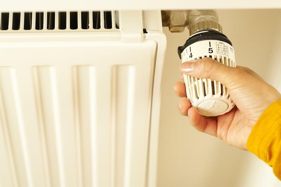
Top-mounted handwheel operators are a prevalent choice for manually controlling valves, particularly those with linear pneumatic actuators. Their positioning allows for intuitive operation and clear visual indication of valve status. These operators typically feature a robust handwheel connected to a stem, converting rotational motion into linear movement to actuate the valve.
They are favored for applications requiring precise control and are often used for throttling or fine adjustments. The design facilitates easy access for maintenance and provides a reliable manual override option when automated systems fail or are unavailable. Proper sizing of the handwheel is crucial for optimal force application and operator comfort.
Air Valve Functionality: Release and Combination Valves
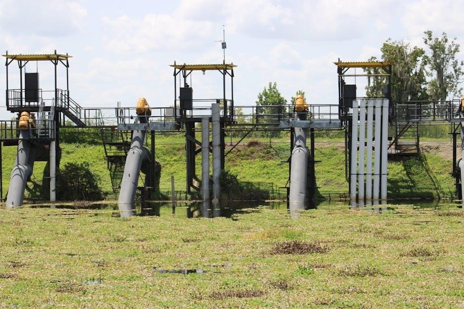
Air valves are critical components in pneumatic systems, managing airflow and ensuring efficient operation. Release valves are designed to automatically discharge accumulated air from pipelines, preventing water hammer and maintaining system pressure. Combination valves integrate multiple functions into a single unit, often combining air release, vacuum breaking, and check valve capabilities.
These valves enhance system reliability by protecting against pressure surges and preventing backflow. Understanding the specific needs of an application – whether it’s simply venting air or providing comprehensive protection – is key to selecting the appropriate valve type. Proper installation and maintenance are vital for optimal performance and longevity.
Pneumatic Valve Basics
Pneumatic valves control the flow of compressed air within a system, acting as essential regulators for various industrial applications. Manual air valves rely on human operation, offering simple and reliable control without the need for electricity or complex automation. Directional control valves, a key type, start, stop, or redirect airflow, enabling precise control of pneumatic actuators and machinery.
These valves are fundamental to processes like automated assembly, packaging, and material handling. Understanding valve types – ball, butterfly, gate, and others – is crucial for selecting the right component for a specific task. Proper sizing and material selection ensure efficient and safe operation within the system’s pressure and temperature limits.

Directional Control Valves in Compressed Air Systems
Directional control valves are pivotal in compressed air systems, dictating the path of airflow to power pneumatic actuators and devices. These valves, often manually operated, determine whether a cylinder extends, retracts, or holds its position. They achieve this by selectively opening or closing ports, directing air to different sections of the system.
Many manufacturing companies leverage compressed air for automation, and directional control valves are at the heart of these processes. Manual versions provide a cost-effective and dependable solution where precise, automated sequencing isn’t required. Understanding port configurations (2/2, 3/2, 5/2, etc.) is key to selecting the appropriate valve for the application’s needs.
Manual Air Valve Specifications
When specifying a manual air valve, several key parameters must be considered. Pressure ratings, typically in PSI or bar, define the maximum allowable upstream pressure. Valve size, indicated by port diameter (e.g., 1/4″, 1/2″), determines flow capacity.
Temperature range dictates the operational limits of the valve, while the body material (brass, stainless steel, etc.) impacts compatibility with the air supply and environment. Connection type (NPT, BSP) ensures proper integration into the existing pneumatic system. Furthermore, consider the actuation type – lever, knob, or push-button – based on user preference and accessibility; Detailed specifications are crucial for optimal performance and longevity.
Installation Procedures for Manual Air Valves
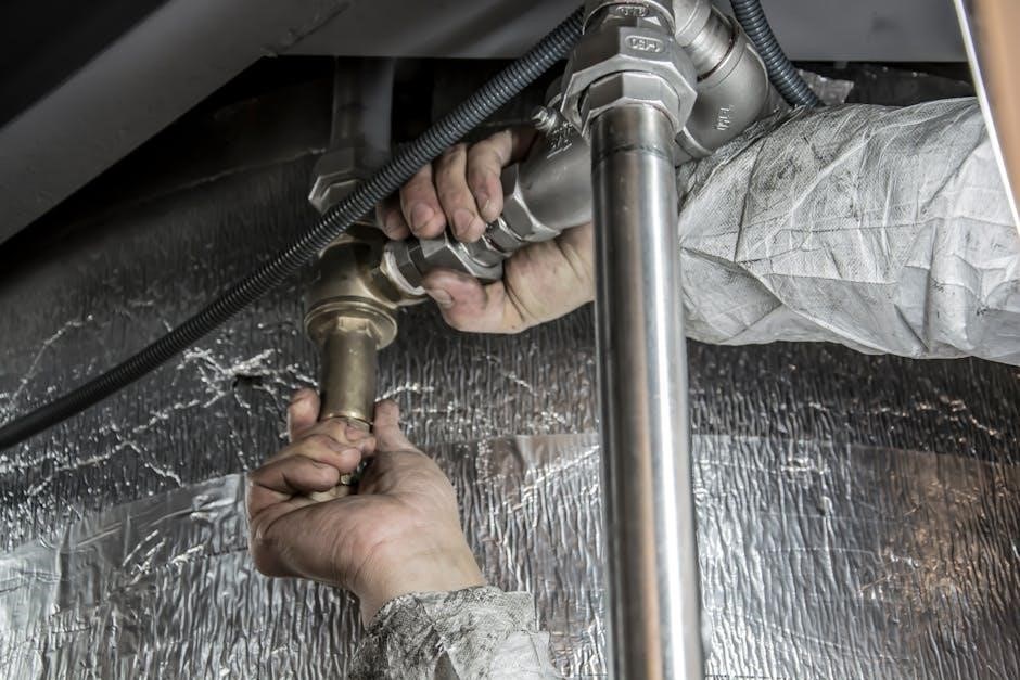
Proper installation is critical for reliable manual air valve operation. Begin by ensuring the system is depressurized and disconnected from the air supply. Clean the pipe threads and apply a suitable thread sealant, avoiding excessive application that could enter the valve.
Carefully align the valve with the piping, tightening connections securely but avoiding over-tightening which can damage the valve body. Support the valve to prevent strain on the connections. After installation, slowly re-pressurize the system and check for leaks around all connections. Refer to the specific installation manual for your valve model for detailed instructions and safety precautions.
Maintenance and Troubleshooting
Regular maintenance extends the lifespan of manual air valves. Periodic inspection for leaks, corrosion, and damage is crucial. Lubricate valve stems and seals as recommended by the manufacturer to ensure smooth operation.
Common issues include leaks due to worn seals or damaged seats, and stiff operation caused by contamination or lack of lubrication. Troubleshooting involves identifying the source of the leak or stiffness, replacing worn parts, and cleaning or lubricating as needed. Always depressurize the system before performing any maintenance. Consult the troubleshooting manual for specific guidance on your valve model.
Common Issues and Solutions
A frequent problem is internal leakage, often stemming from worn or damaged valve seats and seals. Replacement of these components typically resolves this. Stiff valve operation usually indicates contamination or insufficient lubrication; cleaning and re-lubrication are key solutions.
External leaks can arise from loose connections or damaged valve bodies, requiring tightening or component replacement. Difficulty in fully opening or closing the valve may signal obstruction or internal damage, necessitating inspection and repair; Always prioritize safety by depressurizing the system before any troubleshooting. Refer to the specific valve’s troubleshooting guide for detailed instructions.
Safety Considerations When Using Manual Air Valves
Always depressurize the system completely before attempting any inspection, maintenance, or repair work on manual air valves. This prevents accidental release of stored energy and potential injury.
Wear appropriate personal protective equipment (PPE), including safety glasses and gloves, to shield against debris or potential hazards. Ensure the valve is correctly rated for the system’s pressure and temperature. Regularly inspect valves for signs of damage or wear. Never attempt to modify a valve beyond its intended specifications. Proper training on valve operation and safety procedures is crucial for all personnel.
Selecting the Right Manual Air Valve
Choosing the correct manual air valve requires careful consideration of application specifics. Evaluate the system’s operating pressure, temperature, and fluid compatibility.
Determine the required flow rate and choose a valve size accordingly. Consider the type of valve – ball, butterfly, gate, globe, etc. – based on its suitability for the application. For frequent operation, opt for valves with durable seals and ergonomic handles. Prioritize valves meeting relevant industry standards and regulations. Assess the need for features like locking mechanisms or visual indicators. Proper selection ensures efficient, reliable, and safe operation.
Materials Used in Manual Air Valve Construction
Manual air valves utilize diverse materials to ensure durability and compatibility with various applications. Common body materials include brass, stainless steel, aluminum, and cast iron.
Seal materials often consist of PTFE, Viton, or EPDM, selected for their chemical resistance and temperature tolerance. Valve stems are frequently made from stainless steel or hardened alloys for strength. Handles can be constructed from metal or durable plastics. Material selection depends on the fluid being controlled, operating pressure, and environmental conditions. Choosing appropriate materials maximizes valve lifespan and minimizes the risk of failure or contamination.
Understanding Valve Size and Pressure Ratings
Valve size, typically indicated by nominal pipe size (NPS), determines the flow capacity. Larger NPS values allow greater airflow. Pressure ratings, expressed in PSI or bar, define the maximum allowable pressure the valve can withstand safely.
Selecting the correct size and rating is crucial for optimal system performance and safety. Undersized valves restrict flow, while over-sized valves can lead to inefficiencies. Exceeding the pressure rating risks valve failure and potential hazards. Consider both static and dynamic pressures when choosing a valve. Always consult manufacturer specifications for accurate ratings and ensure compatibility with the compressed air system.
Manual Air Valve Standards and Regulations
Adherence to industry standards and regulations is paramount for ensuring safety and reliability in pneumatic systems. While specific regulations vary by region and application, several standards commonly apply to manual air valves.
These include standards related to materials, design, testing, and performance. Manufacturers often certify their valves to meet recognized standards, providing assurance of quality and compliance. Understanding these standards is crucial for selecting valves suitable for specific environments and applications. Proper documentation and traceability are also essential for regulatory compliance and maintenance records.
Resources for Manual Air Valve Documentation
Accessing comprehensive documentation is vital for proper installation, operation, and maintenance of manual air valves. Manufacturers typically provide a range of resources, including owners manuals, detailed installation guides, and troubleshooting manuals.
These resources often include specifications, safety information, and warranty details. Online databases and manufacturer websites frequently host downloadable PDF versions of these manuals. Supplementary materials, such as service technical documentation and user references, can also be valuable. Searching by model number (e.g., GX240, ET-2400) will yield specific documentation for your valve.
Owners Manuals
Owners manuals are the primary resource for understanding your specific manual air valve model; They provide crucial information regarding safe operation, recommended maintenance schedules, and basic troubleshooting steps.
These manuals typically detail the valve’s intended use, component identification, and performance specifications. They often include diagrams illustrating proper installation and connection procedures. Regularly consulting the owners manual ensures optimal valve lifespan and prevents potential hazards. Look for details on warranty information and contact details for customer support. Many manufacturers offer downloadable PDF versions of these manuals online, easily accessible by model number.
Installation Manuals
Installation manuals provide step-by-step guidance for correctly mounting and connecting manual air valves within a compressed air system.
These documents detail essential prerequisites, such as proper pipe sizing and alignment, and emphasize the importance of using appropriate sealing materials; They often include detailed diagrams illustrating correct orientation and securing methods. Following the installation manual precisely prevents leaks, ensures optimal performance, and safeguards against potential damage to the valve or connected equipment. Pay close attention to torque specifications for fasteners and recommended procedures for pressure testing after installation. Downloadable PDF versions are commonly available from manufacturers.
Troubleshooting Manuals
Troubleshooting manuals are indispensable resources for diagnosing and resolving issues with manual air valves, minimizing downtime and repair costs.
These guides typically present common problems – like leakage, stiff operation, or failure to fully open/close – alongside probable causes and systematic troubleshooting steps. They often include diagrams to aid in identifying valve components and potential failure points. Manuals detail how to safely isolate the valve, inspect for damage, and replace worn parts. Following these procedures ensures accurate diagnosis and effective repair. Accessing downloadable PDF versions from manufacturers provides comprehensive support for maintaining optimal valve functionality and system efficiency.
Future Trends in Manual Air Valve Technology
The future of manual air valve technology is leaning towards smarter, more efficient, and integrated solutions.
Expect increased integration with Industrial Internet of Things (IIoT) platforms, enabling remote monitoring of valve status and predictive maintenance scheduling. Material science advancements will yield lighter, more durable valves resistant to harsh environments. Designs incorporating ergonomic improvements for easier operation and reduced operator fatigue are also anticipated. Furthermore, manufacturers are exploring modular designs for simplified customization and faster repair times. Digital twins and augmented reality applications will aid in training and troubleshooting, enhancing overall system reliability and performance.